 Kia Optima: Replacement
| 1. |
Loosen the wheel nuts slightly.
Raise the vehicle, and make sure it is securely supported.
|
| 2. |
Remove wheel nuts, rear wheel
and tire from rear hub.
Tightening torque:88.2
~ 107.8 N.m (9.0 ~ 11.0 kgf.m, 65.0 ~ 79.5 lb-ft)
|

|
Be careful not to damage to the wheel nuts when removing the rear
wheel and tire. |
|
| 3. |
Loosen the mount screw and then
brake disc (A).
Tightening torque:4.9 ~
6.8 N.m (0.5 ~ 0.7 kgf.m, 3.6 ~ 5.0 lb-ft)
|

|
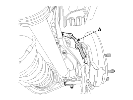
| 4. |
Loosen the rear upper arm and
then remove the rear upper arm (A).
Tightening torque:137.2
~ 156.9 N.m (14.0 ~ 16.0 kgf.m, 101.2 ~ 115.7 lb-ft)
|


|
| 5. |
Remove the brake caliper mounting
bolts , and then hold the brake caliper assembly (B) with wire as shown
in the illustration.
Tightening torque:78.4
~ 98.0 N.m (8.0 ~ 10.0 kgf.m, 57.8 ~ 72.3 lb-ft)
|

|
| 6. |
Disconnect the wheel speed sensor
connector (A).
Tightening torque:6.8 ~
10.7 N.m (0.7 ~ 1.1 kgf.m, 2.8 ~ 7.9 lb-ft)
|

|
| 7. |
Disconnect the parking cable
mounting clip, remove the parking cable (A). (Refer to BR group - "Parking
brake cable")
|
| 8. |
Loosen the trailing arm mounting
bolt, and then remove the trailing arm (A).
Tightening torque:44.1
~ 53.9 N.m (4.5 ~ 5.5 kgf.m, 32.5 ~ 39.7 lb-ft)
|


|
| 9. |
Loosen the assist arm mounting
nut and then remove the assist arm (A).
Tightening torque:44.1
~ 53.9 N.m (4.5 ~ 5.5 kgf.m, 32.5 ~ 39.7 lb-ft)
|

|
| 10. |
Loosen the lower arm (A) and
rear strut (B) mounting bolts and remove the knuckle assembly (C).
Tightening torque:Lower
arm : 137.2 ~ 156.9 N.m (14.0 ~ 16.0 kgf.m, 101.2 ~ 115.7 lb-ft)
Strut : 137.2 ~ 156.9 N.m (14.0 ~ 16.0 kgf.m, 101.2 ~ 115.7 lb-ft)
|


|
| 11. |
Loosen the hub bearing mounting,
and then remove the hub bearing from knuckle (A).
Tightening torque:78.4
~ 88.2 N.m (8.0 ~ 9.0 kgf.m, 57.8 ~ 65.0 lb-ft)
|

|
| 12. |
Install in the reverse order
of removal. |
1.
Check the hub for cracks and
the splines for wear.
2.
Check the brake disc for scoring
and damage.
3.
Check the rear axle carrier for
cracks.
...
See also:
Removal
1.
Remove the battery and the battery
tray. (Refer to "Charging system" in EE group.)
2.
Remove the under cover (A).
Tightening torque:7.8 ~
11 ...
Heater Unit. Repair procedures
Replacement
1.
Disconnect the negative (-) battery
terminal.
2.
Recover the refrigerant with
a recovery/ recycling/ charging station.
3.
When the e ...
Description and Operation
Description
The charging system includes a battery, an alternator with
a built-in regulator, and the charging indicator light and wire.The Alternator has built-in diodes, each rectifying AC curren ...

 Inspection